Sunday, April 25, 2010

Twisty Curvy Curtain Panel Fun

I am sure that many of us are familiar with the Phil Read Twisting Tower (PRTT) idea.  Simple mass family, top surface rotates according to an angle determined by the level/elevation of the piece...looks a bit like this:
 
I remember the first time i saw it, my opinion of Revit changed dramatically for the better.  When i learned how to build it myself, my opinion became even more positive! (Links to tutorials here) 

Good feelings aside, the dynamic form is so very sexy but i always felt limited by its inherently vertical nature.  I understand the relationship to constructability and all that, but i really wanted to push the form to the next level.  Curtain Panel Patterns give me the power.

First, i built a simple mass unit using the same principles as the PRTT, but i used the Curtain Panel By Pattern: RECTANGULAR SURFACE template, building the top and bottom rectangles on the edges of the panel.

Now i can apply these masses as a pattern on a surface.  I created a 4 point curve, attaching parameters to control the curvature, and then extruded a simple surface, dividing it appropriately:
   Then i applied the Rectangular Surface Pattern i had made:

After going through and numbering each individual panel to activate the 'twistyness', I was VERY pleased with the results.  Some of the engineers around me in the office looked at this and shuddered...but i don't care, I am in it for the monkey business!  Maybe i should change my name to CURTAIN PANEL BY PATTERN-TROUBLEMAKER!
With much respect, admiration and thanks to those who have come before me in this work, here is a link to Phil Read's presentation from AU2006 for the basic PRTT technique:
Advanced Autodesk Revit Building Techniques - Phil Read - BD41-3_AU2006.zip

And this link goes to the model of my Curtain Panel by Pattern monkey business:
twisty 3.rfa


Monday, April 19, 2010

Burmese Pagodas, Curtain Panels and Reporting Parameters

One of the perks of being based in Asia is that the travel opportunities are phenomenal.  A Burmese friend invited me to join him for a trip to visit his family in Myanmar.  Of course, I accepted and we spent a few days in Yangon and Mandalay.  At the end of the trip, he took me to a place called Bagan where there is a countless number of 1,000 year old brick pagodas like these:


As i spent the day in a horse drawn buggy, trotting across the desert looking at these forms, I started to wonder how to generate them in Revit.  I took particular interest in the textures and rings of the spires:


After trying a couple of different methods, it ended up being a really neat experiment in the use of curtain panels and the reporting parameters feature in 2011.

So here we go....

First thing i did was set up a pair of 3-point curves which i would use to set-up my elevation profiles.  By attaching parameters to the driving reference points, i could refine the shape later:


Each horizontal line represents a horzontal division of the model.  I will use this to get the stepped effect later on but first i had to place reference points at every intersection.  I simply placed the points on my curve and then pressed the HOST POINT BY INTERSECTION button.  I selected the line i wanted to link for the intersection and it worked like a charm.


Now that point will ALWAYS be where the line and curve intersect....And I can now put a reporting parameter to it that will come in handy later:
Next i had to make my curtain panels using the Panel Pattern Templates.  First i made a slab and a disc mass family:


Then nested these in to an OMNI GRID 2x2 Panel Pattern:


The 'Panel_HT' Paramenter is actually a reporting parameter that will be used to control the height of each Pattern Panel in the final model.  This is the Patterns after the nested parameters have been linked:


With this accomplished, I go back to my profile model and set up a pair of surfaces to divide and apply my pattern:
Now i go through and pick each panel individually and link its width to the reporting parameters i set up along the curve earlier in the exercise.  The end result looks like this:


Several of my Hindu and Buddhist colleagues got a real kick out of seeing this model on my computer screen as the work progressed.  They all had a deep religious connection to forms like this.

At the end of the exercise i noticed something very interesting as well, By burrowing down into my selection, I could actually divide the surfaces that made up the individual slabs....This would allow me to apply further textures and ornament to each individual panel element....This is a rabbit hole that goes down pretty far!

Model for Download:
More pictures from Burma:

Monday, April 5, 2010

Nested Structural Elements: It's Just a Bad Idea or God Hates Me

I like consistency in my software, and Revit gives it to me in abundance....I am consistently beating my head against a wall because Revit doesn't do what I want it to, especially when it comes to nesting structural columns and beams in families.

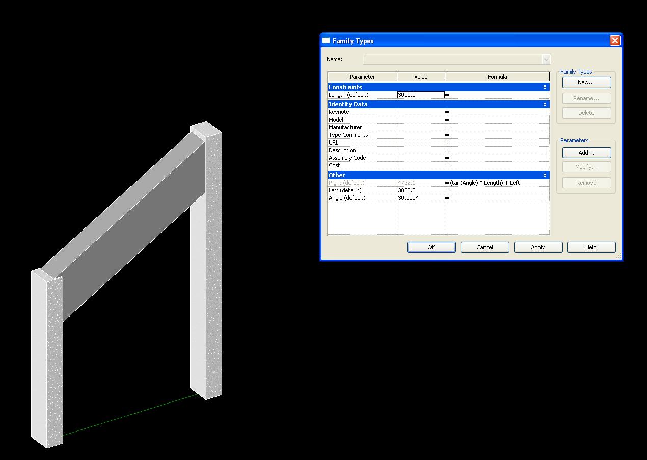
This mess came from an attempt to sort out a post and beam family where a parameter controlled the distance between the columns while an angle parameter controlled the beam slope and column heights.

First I tried it as a line based family.  The columns were aligned and then locked to the reference planes.  A parameter was set to control the height of the columns and beam start/end points.

This worked great until i added the angle parameter....


Just like they said in CLASH OF THE TITANS, The God's move in unpredictable ways...

So I tried again....this time using a generic template, to see if i could get different results....

This is what it looked like in plan with my columns locked to reference planes:

Then checked out the flexing...

Looks good so far....or is it?  I brought it into a REVIT STRUCTURE project:


Looked dynamite....except for one small hitch, I can't snap to the structural elements!
Why?
Because the elements aren't shared.
Why?
Because structural element families don't have the SHARED box ticked.
Why?
I don't know, but if I tick the box myself, nest a column or beam in a family, and then import that family, i get a very ugly error message:


Looking at this mess side-by-side with my non-existent love life, I become convinced that god indeed hates me.

Models are here:

structural meshugas_Line based.rfa
structural meshugas_generic.rfa

Monday, March 29, 2010

Mobius Stripping: Adventures in Infinity

I was at an art exhibit over the weekend and one of the artists was exploring the relationship between the finite and the infinite.

He postulated that the simplest finite expression we have is bianary language.  ON or OFF.  Yes or NO. 0 or 1.  And from those simple choices, stacked one on top of the next, we reach infinity.  Which got me thinking about computers and Revit.  I had never given much thought to the idea that everything we do on our computers boils down to a binary expression....and from those simple choices, stacked one on top of the next, we develop our work, our designs, our lives...out to infinity.  The concept stuck with me.

So in the spirit of the infinite, I wanted to look at how REVIT would deal with a MOBIUS STRIP....and thus far, I found that it deals with the form poorly.  But it did generate some of the wackiest errors I have seen so far while using the program....like this one:


First I tried the easy way.  I swept a rectangle along a 180degree arc, rotated one end of the the form, and then made a mirror copy.


In essence it worked, but there were 2 problems. First, the ends of the form didn't blend very well, and Second, I was looking to make the impossible, a flat one sided object! I consider extruding a solid along a path, no matter how thin the solid, to be cheating.


My next attempt involved trying to stich some reference lines together.  I made a rig to 3d-Snap the curves to.  I was able to get 87.5% around the path like this:

But in the end, it didn't work either...I got a deformed clam shape that you'll see at the end of this movie:


My last attempt is as close as a i came to success.  First I made an arc surface family that i could also control the rotation angle of its ends.


Then i nested 8 of them together, worked out the connection angles and it worked pretty nicely.


The edges still don't blend perfectly but it got close enough to satisfy me...for now.


Hmmmm....Conquering the Infinite with Revit Architecture!!!!

Somebody call Carl, I smell a slogan for AU next year... 

3D Models to Share:

Mobius Strip Segmented.rfa
Mobius Strip from reference lines.rfa

Thursday, March 11, 2010

Of Venetian Blinds and Job Seeking

At the Huay Kwang Headquarters of the BIMTROUBLEMAKER GLOBAL MINISTRIES, the mailbox is always busting. We love mail about as much as we love late night bbq pork and papaya salad feasts.

The other day we received another cv by email, ”Hey troublemaker can you help me find a job….blah blah blah….” And these inquiries usually get ignored…But this one was a bit different.

2 things got my attention about this joker.

1)  His CV shows a good deal of construction and design side credibility, but on the list for his work experience, he mentions his time managing a TATTOO PARLOR/PIERCING STUDIO. This guy snowboards competitively AND can program in C+! To me, this sounds like a winning combination.

2)  He sends me a Revit file and says it’s a “showcase of his skills”. I was pretty sceptical about this, until I opened the file. Yowza! Checkout his list of parameters, he obviously knows his way around when it comes to programming families.

These are some .JPGs of the work and a link to download the model.


My current organization already has a resident Revit Smart-A$$ (aka: ME) but this guy looks interesting and capable and I would hire him I could.

So with that in mind, I am gonna give a plug to Egils Bernovskis. If your organization is looking for a Troublemaker, this guy might fit the bill. Drop me a line at bimtroublemaker@gmail.com and I will gladly make the connection.

Good luck with the job hunt Egils!


Wednesday, March 3, 2010

Curtain Panels: Curved Shading Elements

A lot of what I have learned about Revit has come from trying to recreate existing buildings in a parametric environment.  This is the Singapore Performing Arts Centre which was designed in the late 1990’s and opened in 2002.

What interests me are the shading elements on the glass since This building was done long before we had Revit’s curtain panel elements! I know it’s hard to believe there was architecture before Revit, but somehow, someone managed to do this…and I’ll bet they had a headache when they were finished!
I wanted to investigate how the curtain panel by pattern tool could help me approximate these shading elements…it was surprisingly easy.  First make the panel,
Then apply it to the surface,
Links to these models are at the end of this post. This movie shows me creating the panel and applying it to the curvy surface:


By paramerizing the hieght and angle of the shade, i can then study how much light is allowed to pass through, and adjust the design to optimize shading based upon orientation.


Links to these models: