First step is to do this with a curtain panel by pattern:
If you don't know what it is, shame on you! Go read here:
So with that panel pattern in my back pocket, i could go ahead and start screwing around with my base model from last time:
For what became my first attempt (thought this would be easy), I started by picking the edges between each rib and hitting the CREATE FORM button.
I did this several times to fill the whole boat
And then divided the surface and applied the appropriate Curtain Panel Pattern:
It looked okay at first blush, but upon closer inspection, the shell edges weren't squaring up right. Actually, they looked downright sloppy:
I'd rather be accused of fastidiousness than having too much time on my hands...Semantic argument for sure....nonetheless i tried again.
This time I took the "Tedious Brute Strength" approach. First off, i hosted a bunch of reference points along the shell profile:
And repeated this process for all 3 profiles and it worked exactly as i wanted:
Then I hosted a parameter driven rectangle on each reference point. CREATE FORM again and voila!
It worked as expected,
but 2 problems remained:
1) All my lengths were now curved and i wanted straight segments, broken at each joint for scheduling and measurement
2) It was a damn lot of work and i got bored
Okay...Trial #3!
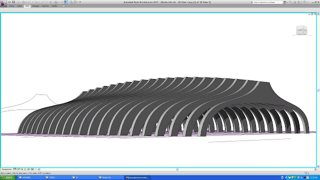
Because I set up the original Curtain Panel Pattern using the correct point orientation, I realized i could do the whole shell in one shot. The trick was going to be to use DIVIDE BY INTERSECTION in order to control the break points:
My segments divide out properly. If i did some work with reporting parameters, I could get some cool data out of this. Implanting MODEL LINES in the curtain panel would give me a structural stick model too!
The joints go straight through which i am not overly keen on, but i suppose if i wanted it perfect, i could take it into Rhino or ACAD and perform some additional boolean operations...
yikes....what a day....


