Sunday, April 25, 2010

Twisty Curvy Curtain Panel Fun

I am sure that many of us are familiar with the Phil Read Twisting Tower (PRTT) idea.  Simple mass family, top surface rotates according to an angle determined by the level/elevation of the piece...looks a bit like this:
 
I remember the first time i saw it, my opinion of Revit changed dramatically for the better.  When i learned how to build it myself, my opinion became even more positive! (Links to tutorials here) 

Good feelings aside, the dynamic form is so very sexy but i always felt limited by its inherently vertical nature.  I understand the relationship to constructability and all that, but i really wanted to push the form to the next level.  Curtain Panel Patterns give me the power.

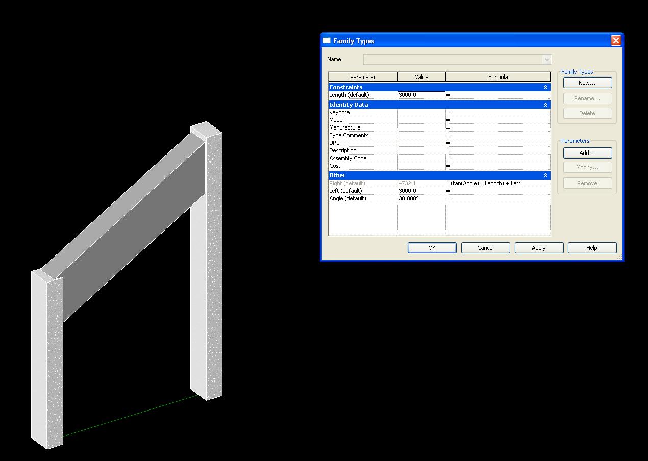
First, i built a simple mass unit using the same principles as the PRTT, but i used the Curtain Panel By Pattern: RECTANGULAR SURFACE template, building the top and bottom rectangles on the edges of the panel.

Now i can apply these masses as a pattern on a surface.  I created a 4 point curve, attaching parameters to control the curvature, and then extruded a simple surface, dividing it appropriately:
   Then i applied the Rectangular Surface Pattern i had made:

After going through and numbering each individual panel to activate the 'twistyness', I was VERY pleased with the results.  Some of the engineers around me in the office looked at this and shuddered...but i don't care, I am in it for the monkey business!  Maybe i should change my name to CURTAIN PANEL BY PATTERN-TROUBLEMAKER!
With much respect, admiration and thanks to those who have come before me in this work, here is a link to Phil Read's presentation from AU2006 for the basic PRTT technique:
Advanced Autodesk Revit Building Techniques - Phil Read - BD41-3_AU2006.zip

And this link goes to the model of my Curtain Panel by Pattern monkey business:
twisty 3.rfa


Monday, April 19, 2010

Burmese Pagodas, Curtain Panels and Reporting Parameters

One of the perks of being based in Asia is that the travel opportunities are phenomenal.  A Burmese friend invited me to join him for a trip to visit his family in Myanmar.  Of course, I accepted and we spent a few days in Yangon and Mandalay.  At the end of the trip, he took me to a place called Bagan where there is a countless number of 1,000 year old brick pagodas like these:


As i spent the day in a horse drawn buggy, trotting across the desert looking at these forms, I started to wonder how to generate them in Revit.  I took particular interest in the textures and rings of the spires:


After trying a couple of different methods, it ended up being a really neat experiment in the use of curtain panels and the reporting parameters feature in 2011.

So here we go....

First thing i did was set up a pair of 3-point curves which i would use to set-up my elevation profiles.  By attaching parameters to the driving reference points, i could refine the shape later:


Each horizontal line represents a horzontal division of the model.  I will use this to get the stepped effect later on but first i had to place reference points at every intersection.  I simply placed the points on my curve and then pressed the HOST POINT BY INTERSECTION button.  I selected the line i wanted to link for the intersection and it worked like a charm.


Now that point will ALWAYS be where the line and curve intersect....And I can now put a reporting parameter to it that will come in handy later:
Next i had to make my curtain panels using the Panel Pattern Templates.  First i made a slab and a disc mass family:


Then nested these in to an OMNI GRID 2x2 Panel Pattern:


The 'Panel_HT' Paramenter is actually a reporting parameter that will be used to control the height of each Pattern Panel in the final model.  This is the Patterns after the nested parameters have been linked:


With this accomplished, I go back to my profile model and set up a pair of surfaces to divide and apply my pattern:
Now i go through and pick each panel individually and link its width to the reporting parameters i set up along the curve earlier in the exercise.  The end result looks like this:


Several of my Hindu and Buddhist colleagues got a real kick out of seeing this model on my computer screen as the work progressed.  They all had a deep religious connection to forms like this.

At the end of the exercise i noticed something very interesting as well, By burrowing down into my selection, I could actually divide the surfaces that made up the individual slabs....This would allow me to apply further textures and ornament to each individual panel element....This is a rabbit hole that goes down pretty far!

Model for Download:
More pictures from Burma:

Monday, April 5, 2010

Nested Structural Elements: It's Just a Bad Idea or God Hates Me

I like consistency in my software, and Revit gives it to me in abundance....I am consistently beating my head against a wall because Revit doesn't do what I want it to, especially when it comes to nesting structural columns and beams in families.

This mess came from an attempt to sort out a post and beam family where a parameter controlled the distance between the columns while an angle parameter controlled the beam slope and column heights.

First I tried it as a line based family.  The columns were aligned and then locked to the reference planes.  A parameter was set to control the height of the columns and beam start/end points.

This worked great until i added the angle parameter....


Just like they said in CLASH OF THE TITANS, The God's move in unpredictable ways...

So I tried again....this time using a generic template, to see if i could get different results....

This is what it looked like in plan with my columns locked to reference planes:

Then checked out the flexing...

Looks good so far....or is it?  I brought it into a REVIT STRUCTURE project:


Looked dynamite....except for one small hitch, I can't snap to the structural elements!
Why?
Because the elements aren't shared.
Why?
Because structural element families don't have the SHARED box ticked.
Why?
I don't know, but if I tick the box myself, nest a column or beam in a family, and then import that family, i get a very ugly error message:


Looking at this mess side-by-side with my non-existent love life, I become convinced that god indeed hates me.

Models are here:

structural meshugas_Line based.rfa
structural meshugas_generic.rfa