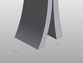
I came to Singapore in 2007 to work on the Marina Bay Sands project. the building was designed by Moshe Safdie and Associates. Moshe assembled a very talented and dedicated team of designers to put all the pieces together. The design for the forms was done in late 2006 into 2007 using Rhino, 3D Max and Maya. At the time, Revit had yet to introduce the conceptual massing environment. I've often wondered what the process for generating these forms would have been like had it been done using the more recent capabilities of Revit. So i did some studying...
Let me be clear at the outset that i don't intend to get these exactly right. I know there was considerable effort, deliberate nuance and extraordinary care that went into the development of this design. My intention is to use the forms as examples for a lesson in how we can use Revit's conceptual massing in the form-finding process.
Part 1: The Hotels
As you can see from these images, the hotel towers are dynamic and morph in all directions as the rise up.
To try and replicate the geometry, the first thing I did was make a rectangle in the conceptual massing environment with key parameters controlling thickness, left & right offset and the shift from the main axis. All of these are INSTANCE parameters.
The next step is to take this profile and nest it into a new conceptual mass family containing 4 levels. Paste the family to all three levels.
After linking parameters to all the profiles, I created the forms, one for the "City" side, one for the "Ocean" side.
And now the fun can begin! Tweaking the parameters like so:
will yield the following results:
Not bad for a start...but because of the way Revit joins geometry, the top portions of the tower aren't straight. I don't think Moshe would have settled for such wacky wobbly BS, so lets try another way with an extrusion and some reference points. Aiming for better control. First, the profile:
and the parameters:
Nest it into my family and make the forms:
And we are cooking now! The wacky wobbly is gone!
Now to add some voids to cut the edges. First i place a reference point on a plane which has been constrained relative to the length of the towers.
I used offsets linked to given dimensions to setout a bunch of other reference points which in turn makes the profiles for cutoff voids.
After making them into voids:
parameter list for the finished product:
and a link to download the family:
https://drive.google.com/file/d/0B101ixgLlSGXbXBfNmd1cHh4V2c/edit?usp=sharing
man... its nice to be behind the wheel again.


NICE..... Well done...
ReplyDeleteWelcome back BTM!
ReplyDeleteWelcome back you married man :)
ReplyDeleteIMPRESSED WITH SUCH A GOOD CONTENT!!
ReplyDeleteVERY INTERESTING
GREAT WORK
BIM Implementation INDIA